IMU Fundamentals, Part 1: Introduction to IMUs
Dive into the measurement model of a 6-DOF IMU, namely an IMU with a 3-axis accelerometer and a 3-axis gyro.
Devon Morris
Staff Perception Engineer
Nov 27, 2023

Explore our entire IMU Fundamentals Series:
Part 1: Introduction to IMUs
Part 2: Deterministic Error Modeling
Part 3: Stochastic Error Modeling
Part 4: Allan Deviation and IMU Error Modeling
Part 5: Preintegration Basics
If you’d like to be notified of when that next post drops, just follow us on LinkedIn or subscribe to our newsletter.
—
IMU Sensing Fundamentals
In the past 15 years, Inertial Measurement Units (IMU) have become ubiquitous in everyday life. You’re probably carrying at least one IMU on your person at this very moment! IMUs make an appearance in smart phones, smart watches and fitness equipment. The primary purpose of an IMU is to sense motion. To do this, IMUs are equipped with an accelerometer, gyroscope and sometimes a magnetometer. In this post, we’ll dive a bit deeper into the measurement model of a 6-DOF IMU, namely an IMU with a 3-axis accelerometer and a 3-axis gyroscope.
Accelerometer
First and foremost, we must answer the question of “what does an accelerometer measure?” If your inclination is to respond “acceleration,” you’re on the right track, but may be surprised when the stationary accelerometer on your desk returns values of about \(g\). How could the accelerometer be reporting an acceleration if it’s just sitting on your desk?
An accelerometer actually measures mass-specific force, or commonly called specific force — we guess that the name Specific-Force-O-Meter didn’t sit too well with our marketing colleagues. A specific force is simply the force per unit of mass. If the motivation behind this seems confusing, just think of g-force. It’s fairly common to hear a phrase like “the pilot felt a force of 5 \(g\)’s” despite \(g\) having units of acceleration and not force.
So, what specific force does an accelerometer measure? It measures the specific force relative to a free-falling body. Or in other words, if you were free-falling toward the center of the earth, you would observe the accelerometer on your desk accelerating upwards at approximately \(g\).
⚠️ The mass-specific force relative to a free-falling frame is also called proper acceleration. However, we choose to use the naming of “specific force” because:
1. It reflects more accurately what is happening in the accelerometer
2. There is less chance of a naming confusion with coordinate acceleration
The basic principle behind the accelerometer measurement model is that of a damped mass spring system. Specifically, we can think of the accelerometer as a calibrated mass (proof mass) on a spring with a calibrated spring constant and a damper with calibrated damping coefficient. When the accelerometer encounters a force, the proof mass moves and a force sensor registers the magnitude of the force exerted by the spring. Through a factory calibration process, these force measurements can be converted into specific-force measurements.
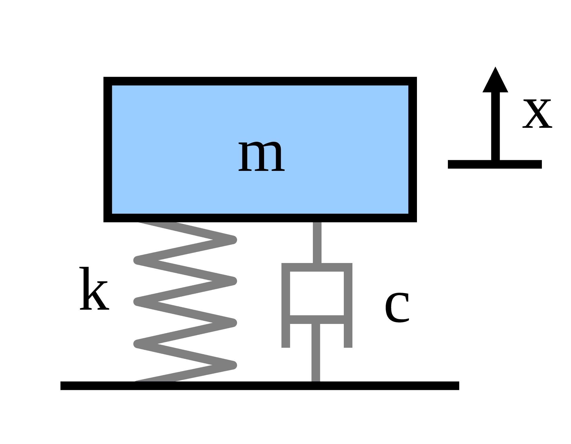
Image Credit: Wikimedia - pbroks13
This principle also provides an explanation for the “acceleration relative to free-fall” property of accelerometers. A stationary mass suspended on a spring will experience zero net force, but the force sensor will register approximately \(mg\) in the upward direction, which is then converted to a specific force \(g\) — Have we mentioned that accelerometers measure specific force and not acceleration?
⚠️ The true inner workings of a MEMS accelerometer are device specific, and often rely on capacitive or piezoelectric sensors to convert mechanical perturbations to analog signals and then into digital signals and finally into an estimate of the specific force. Each of these signal transformations have associated models and assumptions which we will dig into more in the next blog post.
However, we are rarely concerned with inferring the specific force of an object. For most navigation applications, we do really want the coordinate acceleration of the accelerometer. For this, we will choose a simple parametric model
\(f^a(t) =a_{a/i}^a(t) + b_a^a(t) - R_i^a(t) g^i + \eta^a_a(t)\)
Where
\(f^a\) is the measured specific force expressed in the accelerometer coordinate frame
\(a_{a/i}^a\) is the coordinate acceleration of the accelerometer (acceleration of the accelerometer with respect to inertial frame, expressed in the accelerometer frame)
\(b_a^a\) is the time-dependent bias of of the accelerometer expressed in the accelerometer’s frame
\(g^i\) is the gravity vector expressed in the inertial frame
\(R_i^a\) is the time-dependent rotation between the inertial frame and the accelerometer’s coordinate frame
\(\eta_a^a\) is the time-dependent noise associated with the accelerometer expressed in the accelerometer’s frame
Like all models, this will fail to accurately capture certain errors produced by the measurement process. Modeling, characterizing and explaining in depth these errors will be the subject of the following blog posts in this series.
Gyroscope
When you hear gyroscope, you may think “isn’t that a toy for kids?” You are absolutely correct! A gyroscope toy maintains its orientation by the principle of conservation of angular momentum (this is also sometimes called rigidity in space). If you put a gyroscope on some gimbals and attach it to some object, then any change in the orientation of that object can be measured simply by measuring the change in orientation of the object compared to the gyroscope. This is traditionally how gyroscopes have worked. As an example, here is the IMU that was used on the Apollo 11 spacecraft.
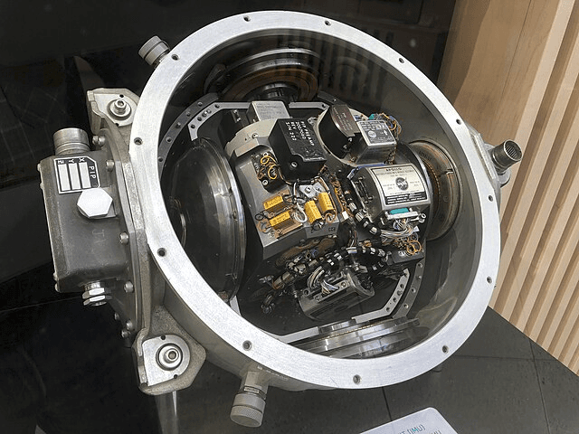
Image Credit: Wikimedia - Arnold Reihold
In short, a gyroscope can be used to measure change in orientation of an object. In the limit as time goes to zero, change in orientation is angular velocity and so we can also say that gyroscopes measure angular velocity of an object.
Modern gyroscopes are obviously not all mounted on a gimbal and use spinning flywheels to maintain orientation. There have been many innovations to gyroscope technology including vibrating structure gyroscopes, ring laser gyroscopes, and even quantum mechanical gyroscopes. For our purposes, most MEMS gyroscopes will be vibrating structure gyroscopes but we can think of them abstractly as black boxes that measure angular velocity.
Again, we will choose a simple parametric model expressing a measurement in terms of a state
$$\tilde{\omega}_{g/i}^g(t) = \omega_{g/i}^g(t) + b_g^g(t) + \eta^g_g(t)$$
Where
\(\tilde{\omega}_{g/i}^g\) is the measured angular velocity of the gyroscope with respect to the inertial frame expressed in the gyroscope frame
\(\omega_{g/i}^g\) is the angular velocity of the gyroscope (angular velocity of the gyroscope with respect to inertial frame, expressed in the gyroscope’s frame)
\(b_g^g\) is the time-dependent bias of of the gyroscope expressed in the gyroscope’s frame
\(\eta_g^g\) is the time-dependent noise associated with the gyroscope expressed in the gyroscope’s frame
Modeling, characterizing and explaining in depth these quantities will be the subject of the following blog posts in this series.
⚠️ In this model and in the accelerometer model, we’ve been very careful to express physical quantities by using three frames
1. The frame that we are measuring
2. The frame that we are measuring with respect to
3. The frame in which we are numerically expressing the measured quantity
We choose to express these quantities like this because it’s unambiguous. Using this notation, it’s very easy to see that \(\omega^g_{g/i}\) may be a different numeric quantity than \(\omega_{g/i}^a\) (although they each represent the same physical quantity). We like to be precise here at Tangram Vision!
Next time, we’ll talk about the deterministic errors associated with these models and how to quantify them. If you’d like to be notified of when that next post drops, just follow us on LinkedIn or subscribe to our newsletter.
—
Edits:
June 2, 2025: Removed links to Tangram Vision's HiFi, a project which has been paused indefinitely.


